

Conveyor Belt Alignment and Misalignment Switch
Conveyor safety accessories designed to alarm and/or shut down conveyor systems in the event of a conveyor belt misalignment.The heavy duty rugged design makes them suitable for most industrial applications. The purpose of the product to reduce time loss, maintenance costs, ensure safety and reduce costs. Conveyor Belt Misalignment Switch is also called Belt Alignment Switch
Showing 1–24 of 159 results
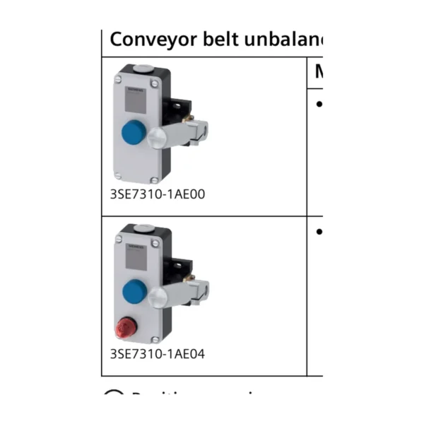
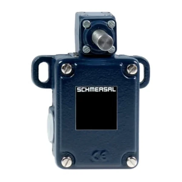
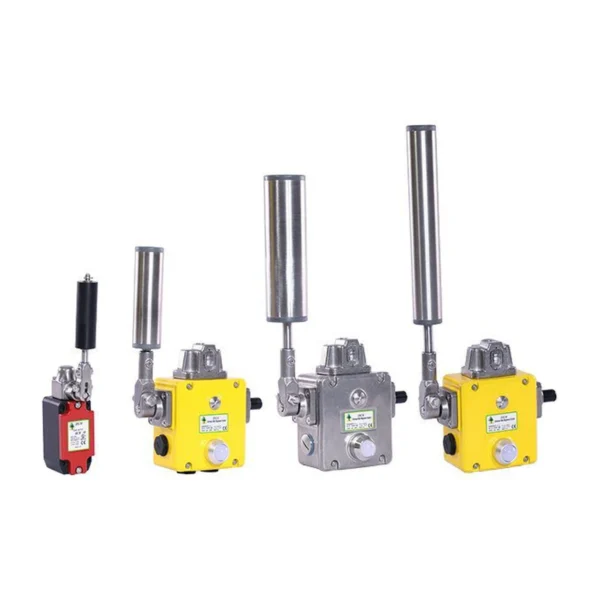


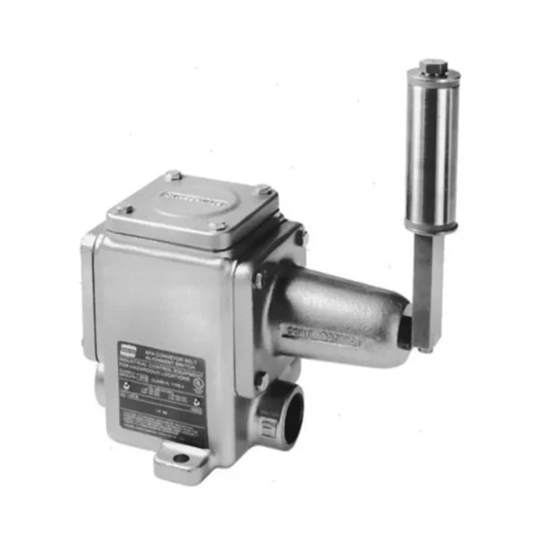
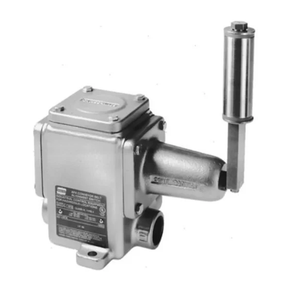


Conveyor belt alignment switches detect excessive side travel and help protect belt edges, structures and material flow from the consequences of poor tracking.
What is a Conveyor Belt Alignment and Misalignment Switch?
Mounted near the belt edge, the roller lever moves when the belt drifts. One contact may provide a pre-alarm and another a final trip, giving operators an opportunity to correct a developing condition before shutdown.
Model suitability depends on the full duty: what changes physically, how quickly it develops, which output is required and what the machine must do next. Two similar housings may differ in contacts, travel, latching, materials or certificates.
Typical applications
Application areas include head and tail sections, convex curves, loading and transfer zones, long conveyor flights. The appropriate construction can change between an indoor panel, an outdoor conveyor, a hot transfer point and a classified dust location even when the basic function is similar.
- head and tail sections: verify the actual operating condition, mounting geometry and required response before selecting a model.
- convex curves: verify the actual operating condition, mounting geometry and required response before selecting a model.
- loading and transfer zones: verify the actual operating condition, mounting geometry and required response before selecting a model.
- long conveyor flights: verify the actual operating condition, mounting geometry and required response before selecting a model.
How to select the right model
For a new application, specify geometry and response from the conveyor design. For a replacement, capture the complete old code, terminals, actuator and mounting before removal, then verify any proposed successor against the original function.
Create an equipment record containing the full model code, approved datasheet, terminal plan and selected settings. This makes quotations comparable and preserves the engineering basis for later replacement.
- Confirm the contact arrangement, utilization category and control voltage.
- Match the enclosure and ingress rating to dust, water, washdown and corrosion exposure.
- Check ambient temperature, cable entry, mounting dimensions and actuator geometry.
- For hazardous areas, verify the complete certificate and marking for the exact model.
Installation and commissioning guidance
Install a pair at each monitored location and check roller height, angle and clearance against the actual belt path under normal load. The switch is a detector, not a substitute for correcting tracking.
Carry out a controlled acceptance test under the manufacturer’s method. Confirm that reset restores readiness without an unintended start and that any startup bypass expires predictably.
Inspection and lifecycle care
After replacement or adjustment, repeat the relevant acceptance test and update the as-built record. A closed work order should identify the failure cause, not only the part that was changed.
If the device is damaged or its state is uncertain, replace it with a verified configuration and inspect the target or process condition that caused the damage. Like-for-like replacement alone may reproduce the failure.
Specification, commissioning and lifecycle record
A dependable conveyor belt alignment switch decision remains traceable from the operating requirement to the installed order code. Record the normal condition, abnormal trigger, required controller state, alarm or stop response, reset rule and inspection method before requesting quotations. This prevents commercial substitutions from changing the engineering function unnoticed.
Keep the approved datasheet, complete model suffix, terminal drawing, mounting sketch, certificates and commissioning result under the equipment tag. After replacement, adjustment, conveyor modification or control-software change, repeat the relevant physical proof test and update the as-built record. The test must demonstrate the field device, wiring, controller indication and final machine response rather than only a changing PLC input.
- Compare complete order codes and option suffixes.
- Confirm contact state under normal, actuated and fault conditions.
- Record the installed clearance, angle, tension, threshold or calibration.
- Inspect mounting, cable entries, seals, earthing and access.
- Set maintenance intervals from risk, environment, duty and failure history.
Frequently asked questions
Where should alignment switches be placed?
Typical points include before critical pulleys, loading zones and long or unstable sections, but the conveyor design and risk assessment determine final locations.
What should happen after an alignment trip?
Inspect loading, idlers, pulleys, tension, buildup and the belt edge; correct the cause and test the protective function before restart.
Selection note: verify dimensions, operating principle, electrical data, environmental rating and certifications on the current datasheet for the exact ordered model.