

Limit Switch
An industrial limit switch converts physical machine movement into a repeatable electrical signal. It can indicate an end position, prove that a guard or mechanism has reached its intended state, sequence a process or provide an input to a control system. Correct selection starts with the mechanical duty rather than the contact rating alone. The actuator must suit the direction, speed and amount of travel, while the housing, sealing and mounting must withstand the real environment.
Showing 1–24 of 48 results
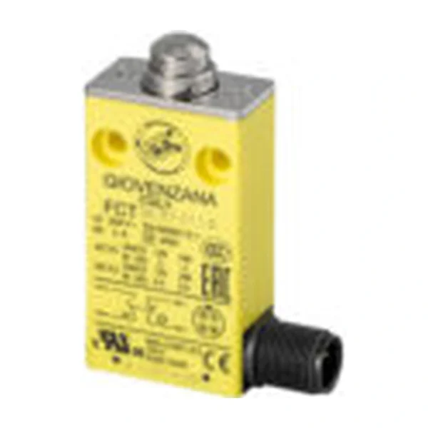
Industrial limit switches convert physical machine movement into repeatable electrical signals for position proving, sequencing, alarm and travel control.
What is a Industrial Limit Switch?
A target operates a plunger, roller lever, whisker, fork or rotary actuator. Internal contacts then change state at a defined point so the controller can confirm position or initiate the specified machine response.
A switch or sensor does not create safety integrity by itself. Its failure behavior, wiring, logic and final control element must be considered together and verified against the performance required by the application.
Typical applications
Relevant installations include conveyor trippers and take-ups, cranes and hoists, guards and access mechanisms, packaging and production machinery. Actual operating observations are valuable: drawings rarely show wind, carryback, washdown, structural movement or the way bulk material strikes a device.
- conveyor trippers and take-ups: verify the actual operating condition, mounting geometry and required response before selecting a model.
- cranes and hoists: verify the actual operating condition, mounting geometry and required response before selecting a model.
- guards and access mechanisms: verify the actual operating condition, mounting geometry and required response before selecting a model.
- packaging and production machinery: verify the actual operating condition, mounting geometry and required response before selecting a model.
How to select the right model
For a new application, specify geometry and response from the conveyor design. For a replacement, capture the complete old code, terminals, actuator and mounting before removal, then verify any proposed successor against the original function.
Include spare strategy and obsolescence handling in the selection. A physically compatible spare is only useful when its contacts, settings, materials and approvals also reproduce the required function.
- operating principle and measurable switching point
- contact arrangement, utilization category and control voltage
- actuator or sensing-element geometry
- enclosure, materials, temperature and cable entry
- hazardous-area or machinery-safety certification where required
- mounting, access, proof testing and replacement traceability
Installation and commissioning guidance
Mount the switch on a rigid bracket and arrange the target to operate the actuator positively without using the switch as a mechanical stop. Confirm approach direction, overtravel and reset under actual machine movement.
Protect the unit from routine impact or burial unless it is designed for direct contact. After termination, inspect gaskets and cable entries and record the initial clearance, tension, setpoint or calibration as applicable.
Inspection and lifecycle care
Inspection combines condition and performance. Compare the field setting with the commissioning baseline, operate the device safely and record the input, alarm, trip and reset results under its unique tag.
Repeated trips are evidence, not inconvenience. Examine the conveyor or process cause before changing delays, clearances or switching angles that may reduce the available protection margin.
Specification, commissioning and lifecycle record
A dependable industrial limit switch decision remains traceable from the operating requirement to the installed order code. Record the normal condition, abnormal trigger, required controller state, alarm or stop response, reset rule and inspection method before requesting quotations. This prevents commercial substitutions from changing the engineering function unnoticed.
Keep the approved datasheet, complete model suffix, terminal drawing, mounting sketch, certificates and commissioning result under the equipment tag. After replacement, adjustment, conveyor modification or control-software change, repeat the relevant physical proof test and update the as-built record. The test must demonstrate the field device, wiring, controller indication and final machine response rather than only a changing PLC input.
- Compare complete order codes and option suffixes.
- Confirm contact state under normal, actuated and fault conditions.
- Record the installed clearance, angle, tension, threshold or calibration.
- Inspect mounting, cable entries, seals, earthing and access.
- Set maintenance intervals from risk, environment, duty and failure history.
Frequently asked questions
How should an industrial limit switch be selected?
Start with target movement, approach direction, speed, travel and required contact behavior; then verify electrical load, enclosure, materials, temperature and approvals on the exact model.
Can a similar-looking limit switch be substituted?
Not without checking the complete order code, actuator, contacts, positive-opening behavior, mounting dimensions, travel limits and environmental ratings.
Selection note: verify dimensions, operating principle, electrical data, environmental rating and certifications on the current datasheet for the exact ordered model.