

Material Flow Switch
A material flow switch provides a discrete indication that bulk material is moving, present or absent at a selected point. It can help prove feed, detect loss of flow, sequence downstream equipment or warn of process interruption. Mechanical paddles and impact plates are common, while some applications use non-contact or electronic principles. Selection must reflect what the control system needs to know: any material presence, sustained flow or a minimum flow condition.
Showing all 10 results
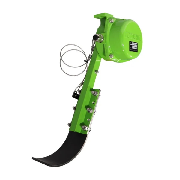
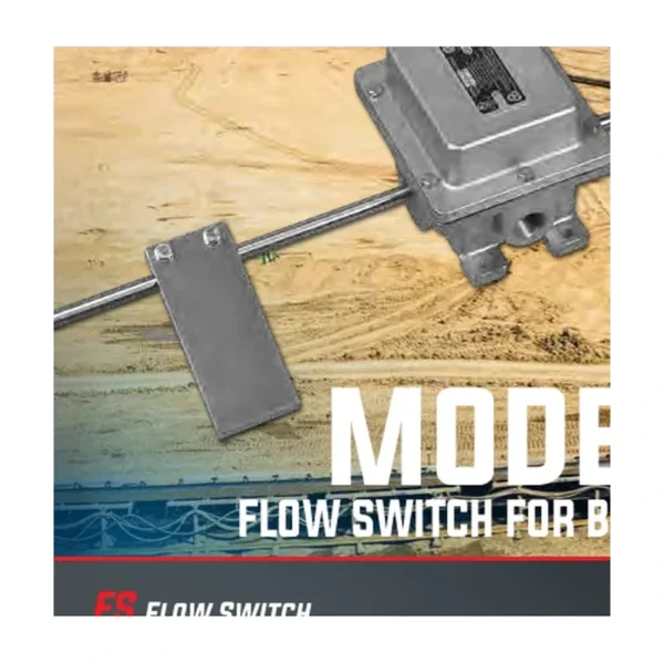
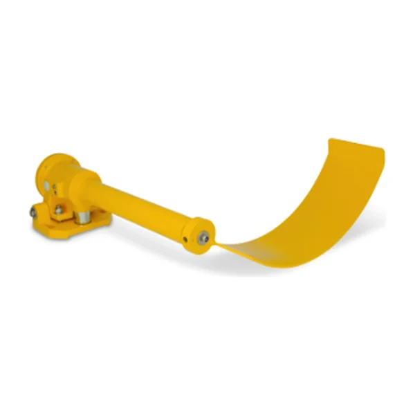
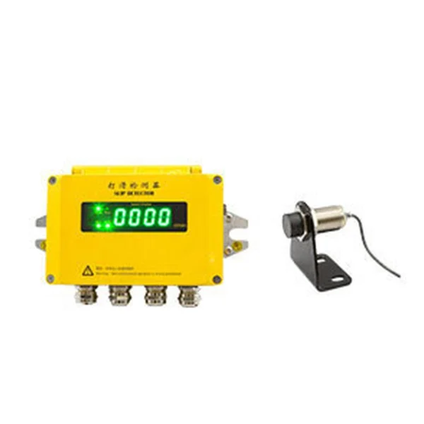
Material flow switches provide a discrete indication that bulk material is moving, present or absent at a selected conveyor, chute or process location.
What is a Material Flow Switch?
A paddle, impact plate or electronic sensing principle responds to the material stream. The resulting contact or electronic output can prove feed, detect loss of flow, sequence equipment or initiate a controlled alarm or shutdown.
Model suitability depends on the full duty: what changes physically, how quickly it develops, which output is required and what the machine must do next. Two similar housings may differ in contacts, travel, latching, materials or certificates.
Typical applications
Common duties include conveyor discharge points, chutes and gravity spouts, feeders and process lines, powder and granular material handling. Each location should be surveyed for material impact, buildup, access, vibration, temperature and exposure before the device and bracket are specified.
- conveyor discharge points: verify the actual operating condition, mounting geometry and required response before selecting a model.
- chutes and gravity spouts: verify the actual operating condition, mounting geometry and required response before selecting a model.
- feeders and process lines: verify the actual operating condition, mounting geometry and required response before selecting a model.
- powder and granular material handling: verify the actual operating condition, mounting geometry and required response before selecting a model.
How to select the right model
Begin with the required process or protective function, then work outward through mechanics, electrical characteristics and environment. Do not assume that products with similar dimensions are interchangeable; actuator movement and contact action can change the control result.
For replacement work, photograph the nameplate and wiring while still legible. For new work, require drawings and certificates with the quotation so configuration suffixes are reviewed before delivery.
- operating principle and measurable switching point
- contact arrangement, utilization category and control voltage
- actuator or sensing-element geometry
- enclosure, materials, temperature and cable entry
- hazardous-area or machinery-safety certification where required
- mounting, access, proof testing and replacement traceability
Installation and commissioning guidance
Place the sensing element in a representative flow path without turning it into a chute liner. Test minimum and normal flow, account for transport delay, and confirm reset after the stream stops.
Verify orientation, target alignment, fasteners, cable route and maintenance access before energization. Commission mechanical response first, followed by terminals, controller indication, alarm or trip and the deliberate restart sequence.
Inspection and lifecycle care
Visual checks should cover loose hardware, bent actuators, seized rollers, cable damage, cracked seals, corrosion and material buildup. Functional tests must prove the controller sees the correct state and produces the intended response.
Any temporary bypass should be authorized, visible and time-limited under site procedure. The repair and subsequent proof test must be completed before the bypass is removed from the management record.
Specification, commissioning and lifecycle record
A dependable material flow switch decision remains traceable from the operating requirement to the installed order code. Record the normal condition, abnormal trigger, required controller state, alarm or stop response, reset rule and inspection method before requesting quotations. This prevents commercial substitutions from changing the engineering function unnoticed.
Keep the approved datasheet, complete model suffix, terminal drawing, mounting sketch, certificates and commissioning result under the equipment tag. After replacement, adjustment, conveyor modification or control-software change, repeat the relevant physical proof test and update the as-built record. The test must demonstrate the field device, wiring, controller indication and final machine response rather than only a changing PLC input.
- Compare complete order codes and option suffixes.
- Confirm contact state under normal, actuated and fault conditions.
- Record the installed clearance, angle, tension, threshold or calibration.
- Inspect mounting, cable entries, seals, earthing and access.
- Set maintenance intervals from risk, environment, duty and failure history.
Frequently asked questions
Does a material flow switch measure flow rate?
Most models provide a discrete flow or no-flow state rather than a calibrated mass-flow value; confirm the operating principle and threshold of the exact device.
How can nuisance trips be reduced?
Choose a representative mounting point and verify sensitivity, damping, material properties, vibration, buildup and normal start-up delay.
Selection note: verify dimensions, operating principle, electrical data, environmental rating and certifications on the current datasheet for the exact ordered model.