

Plugged Chute Switch
A plugged chute switch detects abnormal material accumulation before a blocked transfer point causes spillage, belt damage or an upstream conveyor overload. Devices may use a pressure diaphragm, hinged paddle, tilt probe or another mechanical sensing element. The best technology depends on the chute geometry, material characteristics and the location where a developing blockage produces a reliable force without subjecting the sensor to continuous normal flow impact.
Showing all 8 results
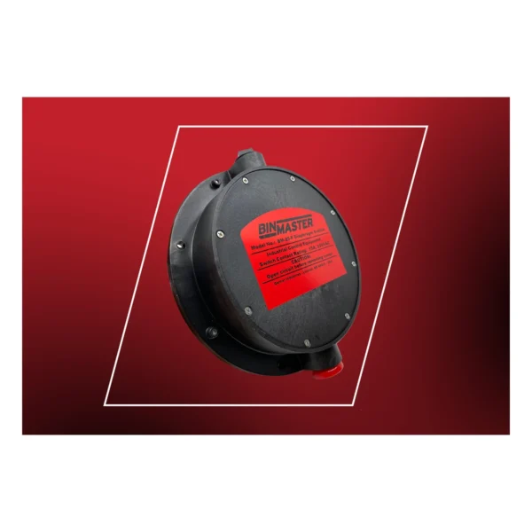
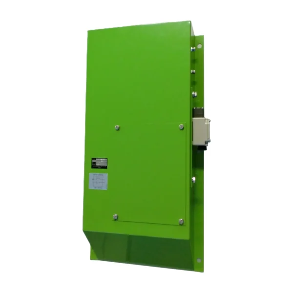
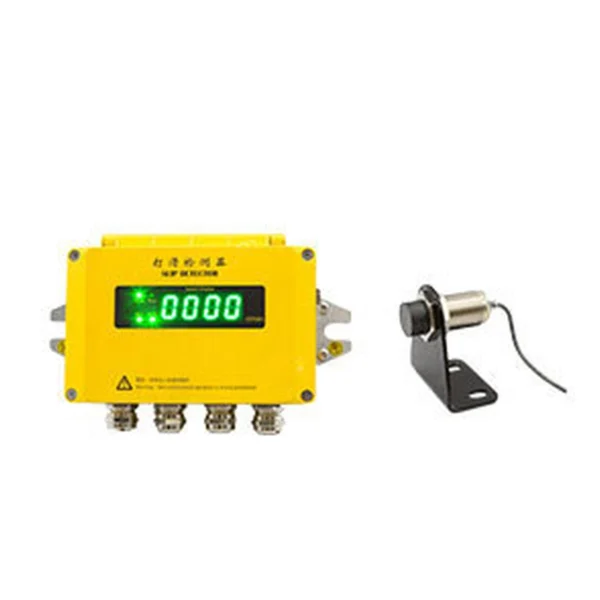
Plugged chute switches detect abnormal material accumulation before a blocked transfer point causes major spillage, belt damage or upstream conveyor overload.
What is a Plugged Chute Switch?
A diaphragm, paddle, tilt probe or other sensing element moves when accumulated material reaches the selected point. The signal warns the control system or stops upstream feed according to the approved cause-and-effect sequence.
Model suitability depends on the full duty: what changes physically, how quickly it develops, which output is required and what the machine must do next. Two similar housings may differ in contacts, travel, latching, materials or certificates.
Typical applications
Relevant installations include conveyor transfer chutes, bucket-elevator inlets and outlets, crusher and screen feed points, bins, hoppers and gravity spouts. Actual operating observations are valuable: drawings rarely show wind, carryback, washdown, structural movement or the way bulk material strikes a device.
- conveyor transfer chutes: verify the actual operating condition, mounting geometry and required response before selecting a model.
- bucket-elevator inlets and outlets: verify the actual operating condition, mounting geometry and required response before selecting a model.
- crusher and screen feed points: verify the actual operating condition, mounting geometry and required response before selecting a model.
- bins, hoppers and gravity spouts: verify the actual operating condition, mounting geometry and required response before selecting a model.
How to select the right model
Use a compliance table to compare candidates against the same requirements. Include operating principle, range or travel, contacts, enclosure, temperature, certification and proof-test method so commercial differences do not hide technical gaps.
Record the proposed mounting point, normal state, alarm or trip action and reset sequence before ordering. A clear cause-and-effect entry prevents different assumptions between mechanical, electrical and control teams.
- operating principle and measurable switching point
- contact arrangement, utilization category and control voltage
- actuator or sensing-element geometry
- enclosure, materials, temperature and cable entry
- hazardous-area or machinery-safety certification where required
- mounting, access, proof testing and replacement traceability
Installation and commissioning guidance
Locate the switch where a developing plug creates a reliable actuation force but normal flow and impact do not hold it continuously. Keep the device accessible for a safe physical proof test.
Set the device only after the conveyor or process is in a correct baseline condition. A protection switch should detect abnormal operation, not compensate continuously for misalignment, unstable loading or poor chute geometry.
Inspection and lifecycle care
Visual checks should cover loose hardware, bent actuators, seized rollers, cable damage, cracked seals, corrosion and material buildup. Functional tests must prove the controller sees the correct state and produces the intended response.
Repeated trips are evidence, not inconvenience. Examine the conveyor or process cause before changing delays, clearances or switching angles that may reduce the available protection margin.
Specification, commissioning and lifecycle record
A dependable plugged chute switch decision remains traceable from the operating requirement to the installed order code. Record the normal condition, abnormal trigger, required controller state, alarm or stop response, reset rule and inspection method before requesting quotations. This prevents commercial substitutions from changing the engineering function unnoticed.
Keep the approved datasheet, complete model suffix, terminal drawing, mounting sketch, certificates and commissioning result under the equipment tag. After replacement, adjustment, conveyor modification or control-software change, repeat the relevant physical proof test and update the as-built record. The test must demonstrate the field device, wiring, controller indication and final machine response rather than only a changing PLC input.
- Compare complete order codes and option suffixes.
- Confirm contact state under normal, actuated and fault conditions.
- Record the installed clearance, angle, tension, threshold or calibration.
- Inspect mounting, cable entries, seals, earthing and access.
- Set maintenance intervals from risk, environment, duty and failure history.
Frequently asked questions
Which plugged-chute sensing principle is best?
It depends on particle size, density, moisture, adhesion, abrasion, temperature, chute geometry and the force available at the mounting point.
Should one chute have more than one switch?
Multiple levels or locations may be justified when geometry creates separate blockage zones or the consequence requires staged warning and shutdown.
Selection note: verify dimensions, operating principle, electrical data, environmental rating and certifications on the current datasheet for the exact ordered model.