

Blog
Types of Conveyor Sensors and Safety Switches

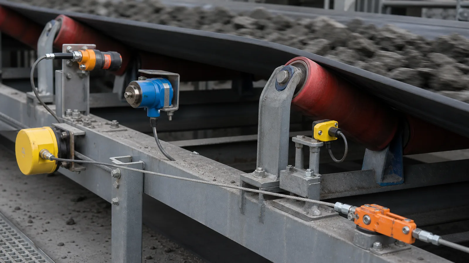
This practical guide examines conveyor sensors from an engineering, installation and lifecycle perspective.
Conveyor protection is layered: each sensor observes a different failure, and no single device replaces the others.
Key takeaways
- Map each credible failure to a detector and control response.
- Separate process measurement from personnel safety functions.
- Choose testable devices with clear fault behavior.
Operating principle and purpose
A conveyor can be moving at the wrong speed, drifting sideways, carrying a torn belt, feeding a blocked chute or placing workers at risk while other signals still look normal. Layered sensing limits the consequence of each condition and provides better diagnostic information.
Mechanical switches give direct, understandable actuation. Proximity and speed sensors provide non-contact pulses. Level devices observe material, load cells measure force and pull ropes provide human-initiated stop access. Integration determines whether outputs create warnings, interlocks or safety-related stops.
Engineering workflow
Convert the application into written requirements before comparing products. A controlled workflow makes technical differences visible and prevents a familiar part number from being applied outside its limits. Include normal and abnormal operating states, who may be exposed, how quickly the condition develops and what the conveyor must do after detection. Mark field locations on a drawing so quotations, installation and later proof tests all refer to the same scope.
- List personnel, equipment and process hazards by conveyor zone.
- Define the earliest observable sign of each failure.
- Select sensor technology that survives the environment.
- Assign alarm, trip, sequence and reset behavior.
- Create a proof-test method and maintenance owner for every device.
Selection and design criteria
Coverage should include field failure and control-system failure. A switch that is impossible to test or whose cable fault appears healthy creates hidden risk. Use independent or diverse sensing where consequence justifies it and document dependencies such as shared power or PLC input cards.
- Pull rope and emergency-stop devices for accessible stop commands.
- Sway switches for lateral belt movement.
- Speed monitors for stall, slip, under- or overspeed.
- Rip and damage detectors for belt failure.
- Tilt, level, position, load-cell and limit devices for process state.
Common failure modes
Most field problems arise from a mismatch between the device, mechanical interface, environment or control logic. Investigate the whole sensing chain before changing settings. Review recent maintenance, process-rate changes, weather and event history, then compare the physical actuator state with the terminal signal and controller indication. A higher delay or wider trip point may silence the symptom while allowing damage or risk to grow.
- Motor current is treated as proof of belt movement.
- One switch is expected to cover an entire long conveyor.
- Process alarms and emergency functions share undocumented reset logic.
- Devices are added without safe access for testing.
- Control tags do not match field labels.
Commissioning and lifecycle verification
Commission the physical device through to the final control action and record the baseline. Inspection frequency should reflect consequence, environment, duty and failure history. Any bypass or failed proof test requires controlled corrective action before normal service. The equipment record should contain the full model code, approved datasheet, mounting photograph, initial settings, normal contact state and cause-and-effect reference. After replacement or adjustment, repeat the relevant acceptance test and confirm that reset restores readiness without issuing an unintended start command.
- Record model, settings, mounting dimensions and terminal state.
- Test the field actuator, input indication, alarm or trip and reset sequence.
- Inspect sealing, cable entry, hardware, actuator freedom and contamination.
- Revalidate after mechanical, electrical, software or process changes.
Specification and verification record
For a repeatable conveyor sensors decision, retain the approved datasheet, model code, mounting or calibration values, wiring reference and observed functional-test result under the equipment tag. Related terminology such as conveyor safety switches, belt conveyor sensors, conveyor protection devices can describe adjacent search or purchasing language, but it must not be used to assume that devices with different functions are interchangeable.
- Record the normal state and the exact condition that creates alarm or trip.
- Photograph the final installation and nameplate before contamination reduces legibility.
- Link every setting change or replacement to an authorized work order.
- Repeat the relevant proof test after mechanical, electrical or software modification.
Frequently asked questions
What sensor detects conveyor belt misalignment?
A belt misalignment, sway or run-off switch located near the belt edge.
What detects a stopped belt?
A speed or zero-speed monitor sensing a pulley or shaft that represents belt motion.
What detects a blocked chute?
Tilt, pressure, capacitance or other point-level detectors selected for the material and geometry.
Are all conveyor switches safety devices?
No. Suitability depends on product design, circuit architecture and the required safety function.
Engineering note: Always verify the selected switch, wiring method, stopping function and environmental rating against the manufacturer’s current datasheet, the machine risk assessment and the standards enforced at the installation location.