

Blog
Conveyor Belt Rip and Tear Detection Methods Explained

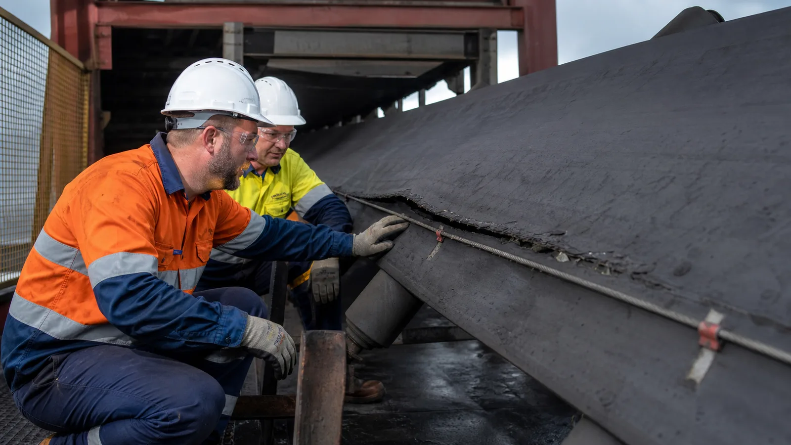
This practical guide examines conveyor belt rip detection from an engineering, installation and lifecycle perspective.
Rip detection is most effective when the sensing method, installation zone and stop response match the way a particular conveyor is likely to be damaged.
Key takeaways
- Loading and transfer zones deserve priority because foreign objects can penetrate the belt there.
- No single detector finds every cut, puncture, splice defect or edge failure.
- Fast detection must be combined with safe stopping dynamics and inspection.
How conveyor belt rips develop
A sharp tramp object can become trapped at a chute or structure and cut the moving belt longitudinally. Protruding steel cords, failed fasteners, torn splices and damaged edges create other failure patterns. Because the belt continues moving, a small penetration can extend rapidly over a long distance.
Detection technologies observe different evidence: a hanging flap displaces a cable or switch, embedded loops are monitored for continuity, non-contact systems look for surface or structural change, and operators identify visible damage during inspection. Coverage and response time depend on detector spacing and the defect path.
Main detection approaches
Select methods from the belt construction, value, speed, loading hazards and acceptable damage length.
- Mechanical tear switches or sensing cables react to protruding flaps or objects beneath the belt.
- Embedded-loop systems detect interruption of conductive loops installed at intervals.
- Magnetic or inductive systems can monitor steel-cord condition or loop signatures.
- Camera and laser systems can identify visible surface anomalies under controlled viewing conditions.
- Routine visual and shutdown inspection remains necessary for defects outside automated coverage.
Designing the protection function
Locate detectors near probable initiation points and calculate how far the belt travels during sensing, logic and stopping. A high-speed, high-inertia conveyor may move a significant distance after the stop command. Coordinate the response with upstream feeders and downstream equipment.
- Belt carcass and splice construction.
- Tramp-material size and likely penetration locations.
- Belt speed, stopping time and acceptable propagation length.
- Spillage, buildup, water and vibration at the detector.
- Testability, diagnostics and repair requirements after a trip.
Why detectors miss damage or false trip
A mechanical cable installed too far from the defect path cannot be displaced; a vision system with a dirty lens cannot see the belt. Each technology has a specific blind spot.
- Assuming one loading-zone detector protects the entire conveyor.
- Allowing routine spillage to hold a mechanical sensor out of position.
- Ignoring damaged embedded loops during belt repairs.
- Using an image system without stable lighting and cleaning.
- Resetting a trip before inspecting both belt surfaces, splice and structure.
Inspection after a rip alarm
Isolate the conveyor and determine the initiating object or structure before moving the belt. Inspect the belt along the possible travel distance, not only at the detector. Follow belt-manufacturer criteria for repair or replacement and verify all detectors before restart.
- Record trip position and belt travel after the stop command.
- Inspect chute liners, scrapers, skirting and return structure for sharp projections.
- Test detectors after belt repair or splice work.
- Trend recurring damage by material source and transfer point.
Specification and verification record
For a repeatable conveyor belt rip detection decision, retain the approved datasheet, model code, mounting or calibration values, wiring reference and observed functional-test result under the equipment tag. Related terminology such as belt tear switch, belt damage detector, longitudinal belt rip can describe adjacent search or purchasing language, but it must not be used to assume that devices with different functions are interchangeable.
- Record the normal state and the exact condition that creates alarm or trip.
- Photograph the final installation and nameplate before contamination reduces legibility.
- Link every setting change or replacement to an authorized work order.
- Repeat the relevant proof test after mechanical, electrical or software modification.
Frequently asked questions
What is a belt tear switch?
It is a field device, often using a cable or actuator, that responds when torn belt material or a foreign object displaces the sensing element.
Can a camera detect a belt rip?
It can detect visible defects within its viewing conditions, but contamination, lighting and hidden damage limit coverage.
Where should rip detectors be installed?
Prioritize loading and transfer zones plus other locations identified by the conveyor damage assessment.
Why is stopping time important?
The belt continues to move after a trip; distance traveled during the stop can determine how far a rip propagates.
Engineering note: Always verify the selected switch, wiring method, stopping function and environmental rating against the manufacturer’s current datasheet, the machine risk assessment and the standards enforced at the installation location.