

Blog
Pull Cord Switch Installation: Design, Tensioning and Testing

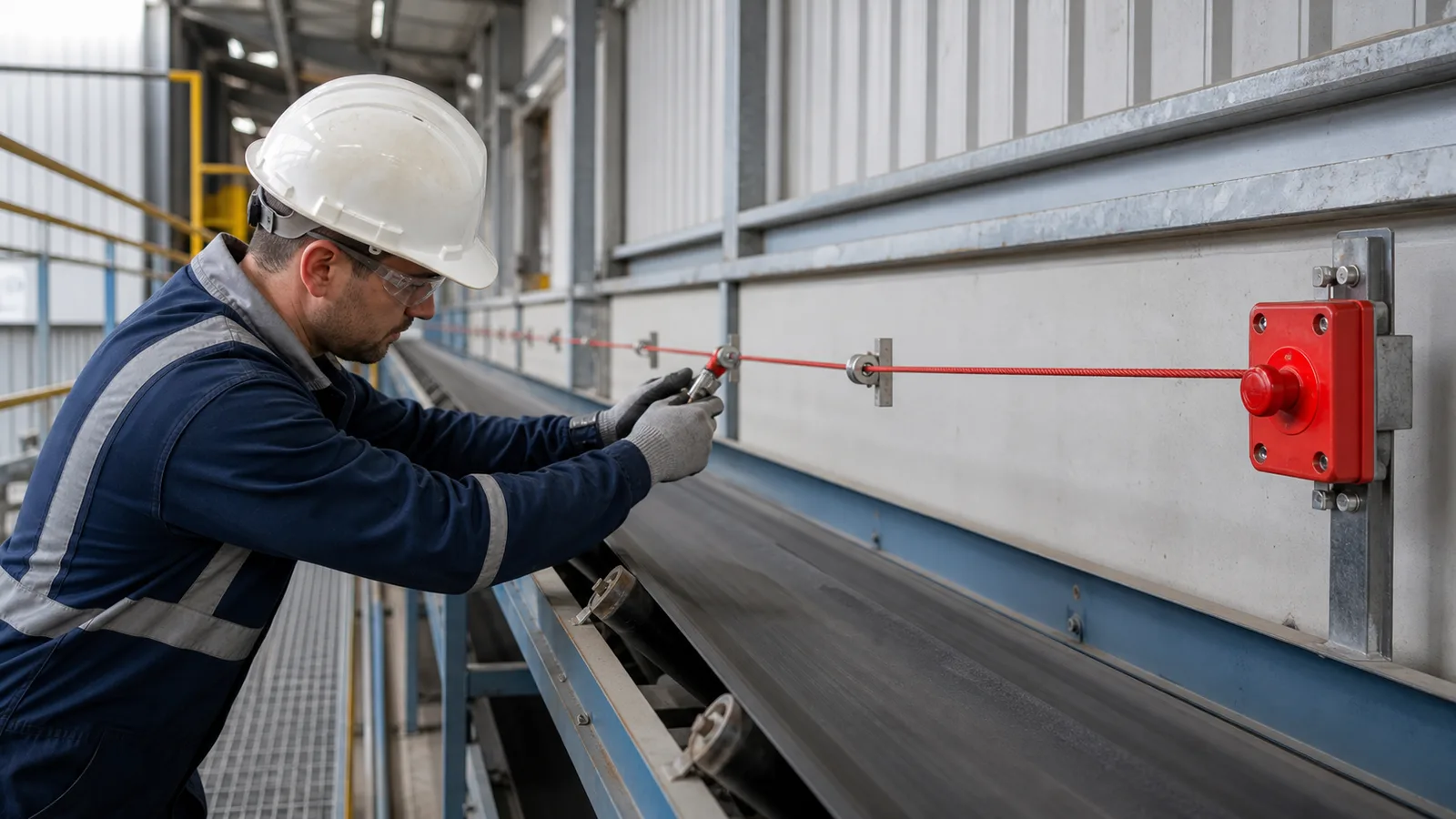
This practical guide examines pull cord switch installation from an engineering, installation and lifecycle perspective.
A pull cord switch is a system, not a standalone box: switch, rope, tensioner, supports, anchors, wiring and stop logic must work together.
Key takeaways
- Use the exact manufacturer limits for rope length, tension and support spacing.
- Engineer access so the rope can be reached without entering the hazard.
- Test pulling, rope fault, latch, reset and restart prevention across the complete run.
How a conveyor pull-rope system works
A tensioned cable extends the emergency stop function along an accessible conveyor route. Pulling the cable rotates or translates the switch mechanism, positively opening stop contacts and typically latching the device. Suitable systems also change state when the rope breaks or loses tension, turning a mechanical fault into a detectable condition.
One-way, two-way and multi-switch arrangements are not interchangeable. The selected geometry determines where springs, end anchors and tensioners belong and how temperature expansion is accommodated. The control circuit then determines the stop category, monitoring and reset behavior.
Mechanical installation sequence
Lay out the complete system on the conveyor drawing before drilling brackets. Include access routes, corners, temperature exposure and structural movement.
- Mount each switch on a rigid bracket in its permitted orientation.
- Install rope supports at the specified spacing and keep the cable within the intended pulling plane.
- Use thimbles, clamps, turnbuckles, springs and tensioners approved for the system.
- Set the cold or reference tension to the indicated operating window.
- Check operating force and travel at the switch, midpoint and farthest accessible locations.
Wiring and safety-function integration
Use the positively operated NC contacts and monitoring architecture defined by the machine design. Separate auxiliary indication from the safety function, maintain cable-gland and earthing requirements and identify every field terminal. Long cable runs may require voltage-drop and fault-detection review.
- Confirm contact arrangement and positive-opening designation.
- Choose latching and reset behavior that supports deliberate inspection before restart.
- Verify enclosure, corrosion and ambient-temperature ratings.
- For hazardous areas, coordinate the exact switch, gland, cable and certificate.
- Document how the control system detects channel and rope faults.
Installation errors to avoid
A system may operate beside the switch yet require excessive force at the far end. That is a mechanical design failure even if the electrical circuit passes.
- Exceeding maximum rope length or support spacing.
- Routing the rope around sharp corners without approved direction-change hardware.
- Using improvised clamps that slip or create broken wire strands.
- Setting tension without considering seasonal temperature change.
- Locating the rope behind guards, stored material or other obstructions.
Commissioning and periodic testing
Commission with the conveyor under controlled safe conditions. Pull from several locations, release or simulate rope fault only by the approved method, confirm latched indication and verify the conveyor cannot restart until the field condition is restored, the switch is reset and a separate start command is given.
- Record baseline tension indicator position and operating force.
- Check supports, anchors, corrosion, fraying and access during inspections.
- Verify both electrical channels and the final stop action.
- Repeat tests after structural, guarding or temperature-related changes.
Specification and verification record
For a repeatable pull cord switch installation decision, retain the approved datasheet, model code, mounting or calibration values, wiring reference and observed functional-test result under the equipment tag. Related terminology such as conveyor pull rope switch, emergency stop cable, pull cord switch testing can describe adjacent search or purchasing language, but it must not be used to assume that devices with different functions are interchangeable.
- Record the normal state and the exact condition that creates alarm or trip.
- Photograph the final installation and nameplate before contamination reduces legibility.
- Link every setting change or replacement to an authorized work order.
- Repeat the relevant proof test after mechanical, electrical or software modification.
Frequently asked questions
How tight should a conveyor pull cord be?
Set it within the exact indicator or force range stated for the selected switch system at the specified reference temperature.
How long can the pull rope be?
Maximum one-way or two-way span is model-specific and depends on supports, springs, temperature and required operating force.
Should a pull cord switch latch?
Emergency-stop arrangements commonly latch so the condition requires local reset, but the required behavior follows the risk assessment and applicable standard.
Can the rope turn a corner?
Only with compatible direction-change hardware and a design that preserves operating force, travel and fault detection.
Engineering note: Always verify the selected switch, wiring method, stopping function and environmental rating against the manufacturer’s current datasheet, the machine risk assessment and the standards enforced at the installation location.