

Blog
Conveyor Protection in Cement Plants

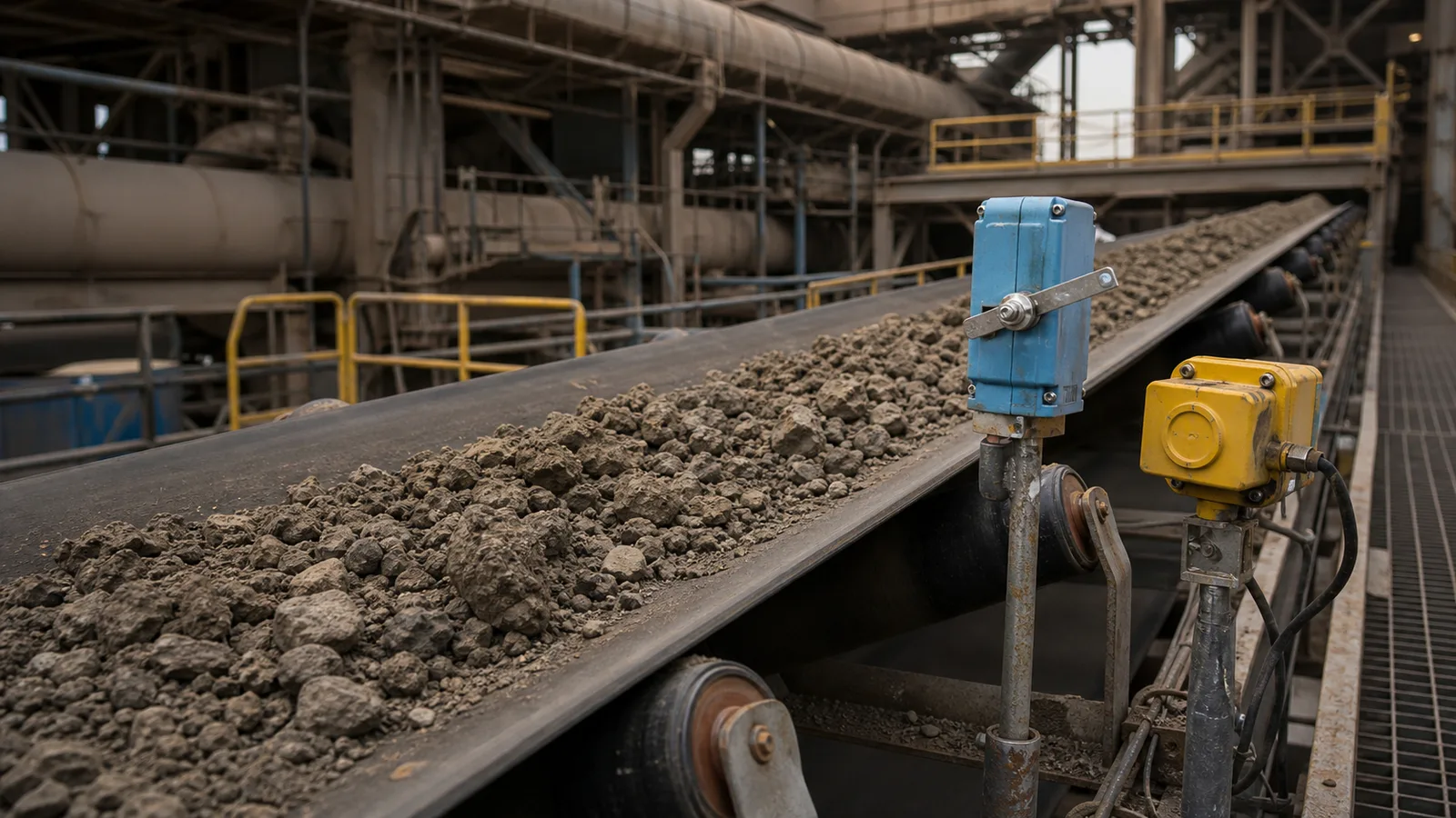
This practical guide examines cement plant conveyor safety from an engineering, installation and lifecycle perspective.
Cement conveyors demand protection that tolerates fine dust, abrasive clinker, buildup, heat and outdoor weather.
Key takeaways
- Separate ambient from product temperature.
- Control dust at cable entries.
- Link blockage to upstream shutdown.
Operating principle and purpose
Limestone, raw meal, cement and clinker create different exposures. Powder enters weak seals, clinker damages actuators and hot material raises local temperature. Buildup changes tracking and can immobilize devices.
Pull ropes protect access routes, sway switches monitor pulleys, speed monitors detect stall, and chute devices stop upstream flow before overflow.
Engineering workflow
Convert the application into written requirements before comparing products. A controlled workflow makes technical differences visible and prevents a familiar part number from being applied outside its limits. Include normal and abnormal operating states, who may be exposed, how quickly the condition develops and what the conveyor must do after detection. Mark field locations on a drawing so quotations, installation and later proof tests all refer to the same scope.
- Classify material and environment.
- Locate buildup and impact zones.
- Choose serviceable actuators.
- Coordinate feeders, elevators and belts.
- Retest after chute or rate changes.
Selection and design criteria
Use matching glands and intact seals. Select abrasion-resistant rollers and probes. Evaluate radiant and conducted heat at switch and cable.
- Dust-tight sealing.
- Abrasion resistance.
- Ambient and process heat.
- Moisture-related corrosion.
- Hazardous classification where applicable.
Common failure modes
Most field problems arise from a mismatch between the device, mechanical interface, environment or control logic. Investigate the whole sensing chain before changing settings. Review recent maintenance, process-rate changes, weather and event history, then compare the physical actuator state with the terminal signal and controller indication. A higher delay or wider trip point may silence the symptom while allowing damage or risk to grow.
- Dust enters an unused opening.
- Buildup holds a sway arm.
- Tilt probe sits in normal flow.
- Cable overheats near chute.
- Alarm stops upstream too late.
Commissioning and lifecycle verification
Commission the physical device through to the final control action and record the baseline. Inspection frequency should reflect consequence, environment, duty and failure history. Any bypass or failed proof test requires controlled corrective action before normal service. The equipment record should contain the full model code, approved datasheet, mounting photograph, initial settings, normal contact state and cause-and-effect reference. After replacement or adjustment, repeat the relevant acceptance test and confirm that reset restores readiness without issuing an unintended start command.
- Record model, settings, mounting dimensions and terminal state.
- Test the field actuator, input indication, alarm or trip and reset sequence.
- Inspect sealing, cable entry, hardware, actuator freedom and contamination.
- Revalidate after mechanical, electrical, software or process changes.
Specification and verification record
For a repeatable cement plant conveyor safety decision, retain the approved datasheet, model code, mounting or calibration values, wiring reference and observed functional-test result under the equipment tag. Related terminology such as cement conveyor switches, clinker conveyor protection can describe adjacent search or purchasing language, but it must not be used to assume that devices with different functions are interchangeable.
- Record the normal state and the exact condition that creates alarm or trip.
- Photograph the final installation and nameplate before contamination reduces legibility.
- Link every setting change or replacement to an authorized work order.
- Repeat the relevant proof test after mechanical, electrical or software modification.
Frequently asked questions
What detects clinker belt drift?
A rugged alignment switch suited to speed, abrasion and temperature.
How is chute blockage detected?
Use point technology selected for the material and geometry.
Does IP66 solve all dust issues?
Only when the complete installation remains sealed.
Why monitor speed?
It detects stall before continued feeding creates a plug.
Engineering note: Always verify the selected switch, wiring method, stopping function and environmental rating against the manufacturer’s current datasheet, the machine risk assessment and the standards enforced at the installation location.