

Blog
Conveyor Belt Sway: Causes, Correction and Protection

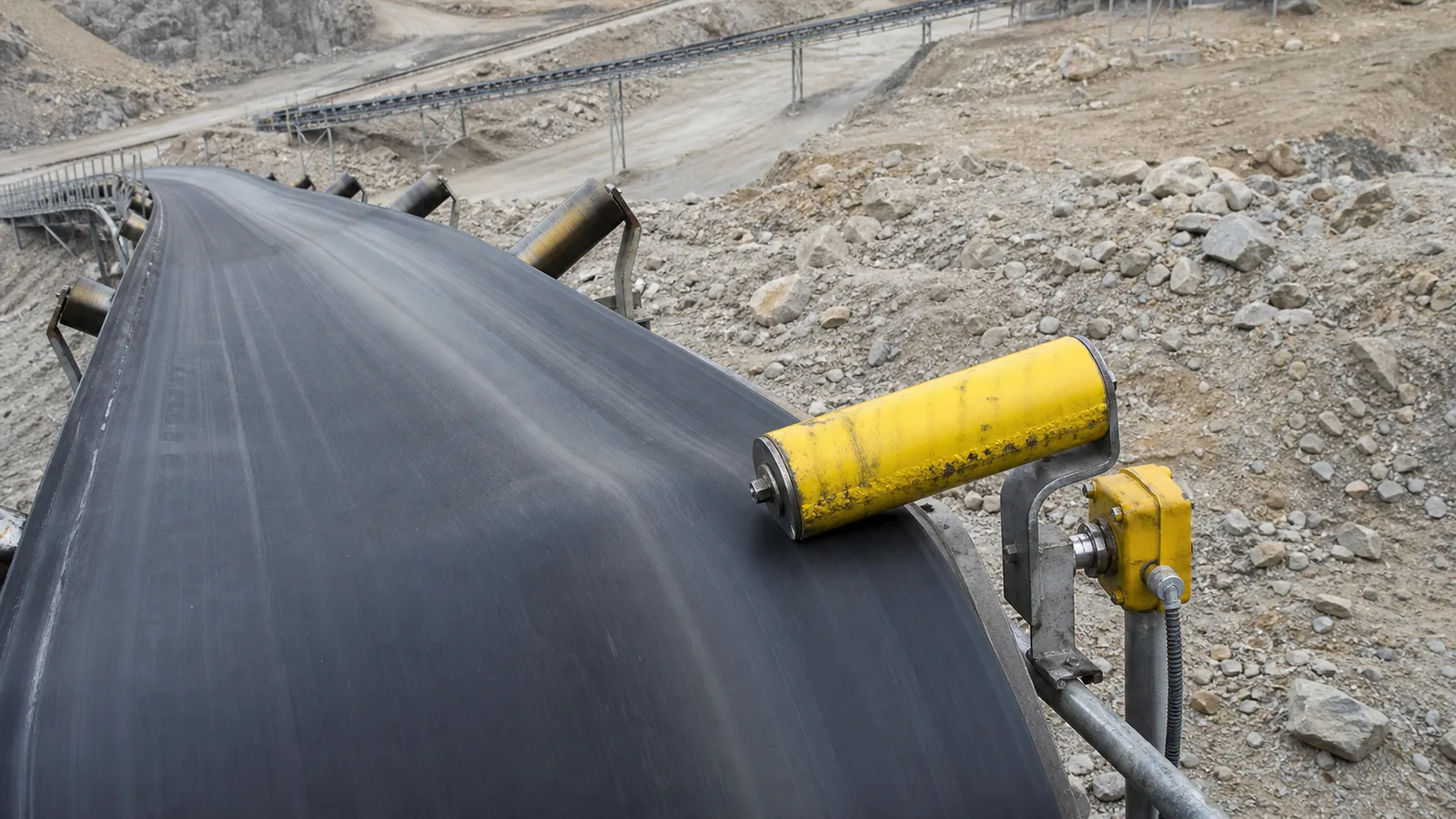
This practical guide examines conveyor belt sway from an engineering, installation and lifecycle perspective.
Belt sway is a symptom; durable correction removes the steering force while switches limit damage if deviation returns.
Key takeaways
- Start where deviation first appears.
- Correct loading and mechanical faults before switch adjustment.
- Confirm behavior empty, loaded and through operating transitions.
Operating principle and purpose
Uneven loading, crooked or seized idlers, pulley misalignment, carryback, wind and uneven tension create lateral steering forces. A belt can track acceptably empty and deviate under load, so observations must cover the conditions that produce the problem.
The belt responds progressively to each component it passes. The rub location may be far downstream from the initiating loading or idler fault. Station-by-station observations and small controlled changes reveal the cause more reliably than large corrective skew.
Engineering workflow
Convert the application into written requirements before comparing products. A controlled workflow makes technical differences visible and prevents a familiar part number from being applied outside its limits. Include normal and abnormal operating states, who may be exposed, how quickly the condition develops and what the conveyor must do after detection. Mark field locations on a drawing so quotations, installation and later proof tests all refer to the same scope.
- Review when, where and under which load the sway occurs.
- Isolate and inspect belt, splice, idlers, pulleys, take-up and structure.
- Correct buildup, seizure, damage and off-center feed.
- Run an authorized controlled test and mark belt position.
- Set protective switches only after acceptable tracking is established.
Selection and design criteria
Consider belt speed, width, trough transition, curve geometry and stopping distance when locating switches. Pair devices on both sides, keep rollers outside normal wander and provide an alarm early enough for intervention before the final trip.
- Loading trajectory and skirt symmetry.
- Idler alignment, rotation and frame condition.
- Pulley axis, lagging and buildup.
- Belt splice, edge, camber and tension.
- Switch clearance, stages and roller condition.
Common failure modes
Most field problems arise from a mismatch between the device, mechanical interface, environment or control logic. Investigate the whole sensing chain before changing settings. Review recent maintenance, process-rate changes, weather and event history, then compare the physical actuator state with the terminal signal and controller indication. A higher delay or wider trip point may silence the symptom while allowing damage or risk to grow.
- Using the roller as a continuous guide.
- Adjusting multiple idlers without records.
- Ignoring wind or rain on an outdoor return run.
- Increasing the trip angle after repeated alarms.
- Restarting without inspecting damaged belt edges.
Commissioning and lifecycle verification
Commission the physical device through to the final control action and record the baseline. Inspection frequency should reflect consequence, environment, duty and failure history. Any bypass or failed proof test requires controlled corrective action before normal service. The equipment record should contain the full model code, approved datasheet, mounting photograph, initial settings, normal contact state and cause-and-effect reference. After replacement or adjustment, repeat the relevant acceptance test and confirm that reset restores readiness without issuing an unintended start command.
- Record model, settings, mounting dimensions and terminal state.
- Test the field actuator, input indication, alarm or trip and reset sequence.
- Inspect sealing, cable entry, hardware, actuator freedom and contamination.
- Revalidate after mechanical, electrical, software or process changes.
Specification and verification record
For a repeatable conveyor belt sway decision, retain the approved datasheet, model code, mounting or calibration values, wiring reference and observed functional-test result under the equipment tag. Related terminology such as belt drift causes, conveyor misalignment, belt sway switch can describe adjacent search or purchasing language, but it must not be used to assume that devices with different functions are interchangeable.
- Record the normal state and the exact condition that creates alarm or trip.
- Photograph the final installation and nameplate before contamination reduces legibility.
- Link every setting change or replacement to an authorized work order.
- Repeat the relevant proof test after mechanical, electrical or software modification.
Frequently asked questions
What causes conveyor belt sway?
Common causes include off-center loading, misaligned or seized idlers, pulley error, buildup, unequal tension, wind and belt defects.
Can sway switches correct tracking?
No. They detect excessive movement and signal alarm or trip.
Why does the belt sway only when loaded?
The load may land off-center or change belt tension and contact with idlers.
Should switches be installed on both sides?
Yes where the belt can deviate either way, following conveyor and manufacturer design.
Engineering note: Always verify the selected switch, wiring method, stopping function and environmental rating against the manufacturer’s current datasheet, the machine risk assessment and the standards enforced at the installation location.