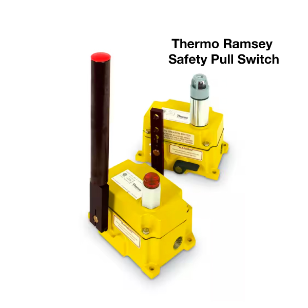
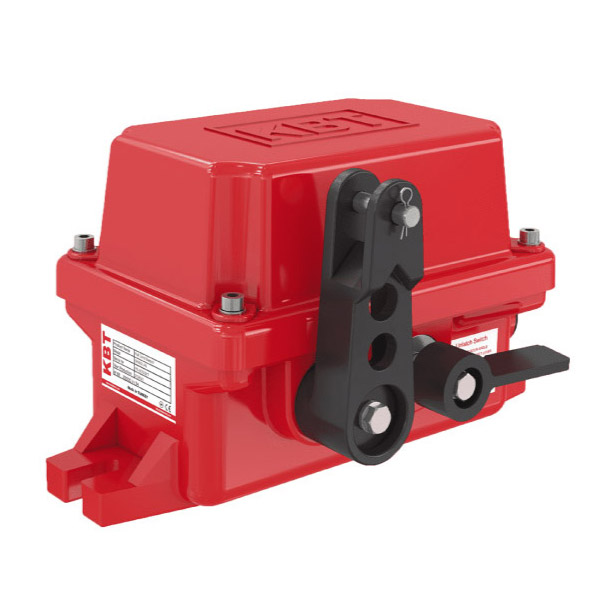
ZS 92 S Emergency Pull Wire Switch
Steute ZS 92 S Pull Cord Switch
- -40°C … +85°C IP66/67 EXTREME
- Temperature resistant from -40 °C to +85 °C
- High degree of protection IP 66 / IP 67 / IP 69
- Corrosion-resistant aluminium enclosure
- Screws made of stainless steel
- Wire length up to 2 x 100 m
- Release by lever
- F = Reset lever at the front side
- B = Reset lever at the back side
- Back and base mounting possible
- Wire pull and breakage detection
- Version with Si-Bus available on request
Steute ZS 92 S Extreme Pull Cord Switch
- -40°C … +85°C IP66/67 EXTREME
- Temperature resistant from -40 °C to +85 °C
- High degree of protection IP 66 / IP 67 / IP 69
- Corrosion-resistant aluminium enclosure
- Screws made of stainless steel
- Wire length up to 2 x 100 m
- Release by lever
- F = Reset lever at the front side
- B = Reset lever at the back side
- Back and base mounting possible
- Wire pull and breakage detection
- Version with Si-Bus available on request
Technical data
| Applied standards | EN 60947-5-1, EN 60947-5-5, EN ISO 13850, EN ISO 13849-1, EN 620:2011-5.7.2.9, AS 1755-2000-2.7.9.1, AS/NZS 4024.3610:2015-2.10.6.2 |
|---|---|
| Enclosure | aluminium, corrosion-resistant, powder-coated, passivated, impact resistant, anthracite grey, similar to RAL 7016 |
| Cover | aluminium, corrosion-resistant, powder-coated, passivated, impact resistant, signal yellow, similar to RAL 1003 |
| Actuating lever | aluminium, corrosion-resistant, powder-coated, passivated, impact resistant, signal red, similar to RAL 3001 |
| Reset lever | aluminium, corrosion-resistant, powder-coated, passivated, impact resistant, sky blue, similar to RAL 5015 |
| Screws | stainless steel |
| Tightening torque | cover screws: max. 2.5 Nm actuator screws: max. 6 Nm |
| Degree of protection | IP 66/67/69 to IEC/EN 60529 |
| B10d (10 % load) | 100 000 |
| TM | max. 20 years |
| Contact material | silver, with Si-Bus: silver, gold-plated |
| Switching system | snap action, positive break NC contacts  |
| Switching elements | 2 NC/2 NO or 3 NC/1 NO contact, type Zb; Si-Bus: 2 NC contacts, type Zb |
| Connection | screw connection terminals; with Si-Bus: screw connection terminals, basic strip to connect Dupline Safe input module with connector (see accessories) |
| Cable cross-section | min. 0.5 mm², max. 2.5 mm² (incl. conductor ferrules) |
| Cable entry | 2 x M25 x 1.5 |
| Rated impulse withstand voltage Uimp | 6 kV; with Si-Bus: 4 kV |
|---|---|
| Rated insulation voltage Ui | 400 V; with Si-Bus: 250 V |
| Conventional thermal current Ithe | 6 A |
| Conditional short-circuit current | 1100 A |
| Rated operating current/voltage Ie/Ue | 6 A/400 VAC; with Si-Bus: 6 A/250 VAC |
| Utilisation category | AC-15 |
| Short-circuit protection | 6 A gG/gN fuse |
| Mechanical life | > 50 000 operations |
| Max. wire length | 2 x 100 m |
| Ambient temperature | –40 °C … +85 ºC Si-Bus: with Si-Bus –40°C … +70°C; without Si-Bus –40°C … +85°C |
| Degree of pollution | 3 |
| Actuating force | actuating lever approx. 30 N; reset lever approx. 40 N |
| Indicator lamp | as option |
| Pressure equalization element | as option |
| Approvals |    |
| ZS 92 S 22 VD F -40°C … +85°C IP66/67 Extreme | stock type | 1457232 |
| ZS 92 S 13 VD F -40°C … +85°C IP66/67 Extreme | 1446778 | |
| ZS 92 S 02 VD Si-Bus F -40°C … +70°C IP66/67 Extreme | stock type | 1364521 |
| ZS 92 S 22 VD B -40°C … +85°C IP66/67 Extreme | stock type | 1456669 |
| ZS 92 S 02 VD Si-Bus B -40°C … +70°C IP66/67 Extreme | 1363023 |
| ZS 92 S 22 VD L F -40°C … +80°C IP66/67 Extreme | stock type | 1277146 |
Application
Emergency pull-wire switches are of great importance for the man-machine interface in the area of industrial applications. They are, for example, applied on transport and conveyor systems. After manual actuation, work and functional processes are initiated or switched off.
When the new harmonised European standard EN ISO 13850 and IEC/EN 60947-5-5 concerning functional aspects and design guidelines for emergency-stop devices has come into effect, new requirements must have to be met by these command devices. All emergency pull cord switches described in this chapter meet the requirements of this standard.
Design and mode of operation
On emergency pull wire switches the emergency-stop command can be initiated from any point along the pull-wire. They have a positive linkage between the NC contacts and the pull-wire. The emergency pull-wire switches are brought into the operational condition by pre-tensioning the pull cord, i.e. the NC contacts are then closed and the NO contacts are open. All devices are equipped with wire-breakage detection. In the chapter accessories the required accessories for installation are presented.
Emergency pull cord switches without mechanical latching VD do not conform to the EN ISO 13850 and IEC/EN 60947-5-5. It is possible to meet the requirements of this standard by suitable measurement of the circuitry and control technology. There are devices with one- and two-side actuation. The wire length, the number of contacts and the mounting position, in the middle or on one side of the system, are the main features when selecting an emergency pull-wire switch.
All emergency pull wire switches bear the CE mark according to the Machinery Directive 2006/42/EC.